Tag Archives: MSL

Coding Like Curiosity – Part 2: Building a Robot

Final form for CurioDuino

In the last post I talked about learning to code in Arduino. This time I would like to talk about hardware. The pieces of hardware that I will be using have already been listed in the previous segment, but I will list them again here.

1. Arduino Uno R3

2. Pololu Zumo Shield with Robot and Reflectance Array

3. Three Sharp Digital Distance Sensors 5cm

4. Adafruit Bluefruit EZ Link Shield with Stacking Headers

Note: The Adafruit EZ Link Shield is only being used for communication currently because the board does not work well for reprogramming across bluetooth yet. (But, Adafruit is still working on it!)

EDIT (4/19/14): Adafruit has fixed their EZ-link!

For reference, here’s a pdf of the Uno board with all of the pins that are in use.

CurioDuino Pin-out

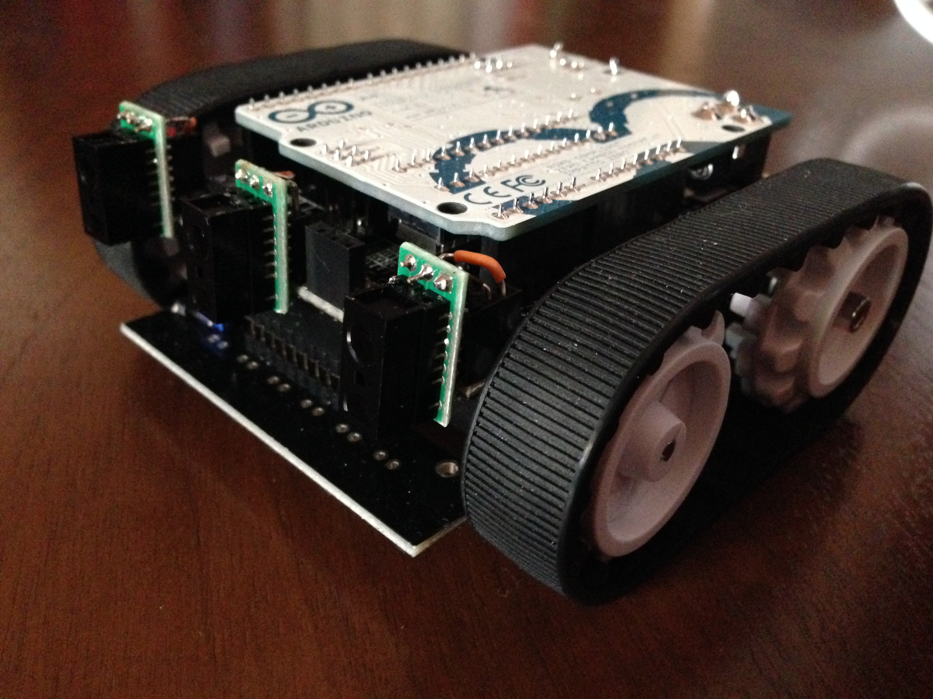
Let’s put CurioDuino together.

The first step is to purchase the ZumoBot chassis and assemble it, along with the Zumo Sensor Array from Pololu. If you read the above pdf carefully, you would notice that is necessary to cut traces between the four inside sensors of the array. Pololu shows how to accomplish this near the bottom of this page: http://www.pololu.com/docs/0J57/2.c

The next step is to get three of the 5cm obstacle sensors listed above. These  will be put into place by soldering using 3 of the 3-pin female adapters into the front expansion of the ZumoShield. The pins that are used for these are listed in the pdf above. There may some confusion with this step. It is truly up to the builder to decide how these sensors will be attached. As long as the data pin is connected to the correct pin shown above, all the code will work correctly. I used a combination of right-angle pins and wire to attach these sensors to the front of CurioDuino.

Once these are in place, slide the the Adafruit Bluefruit EZ Link shield with stacking headers into the pins of the ZumoShield.  Lastly, place the the Arduino Uno on top of the EZ Link. At this point, you have a fully assembled CurioDuino. All that is left is to upload the code to the Uno. Before doing this, ensure that the switch on the front of the EZ-link shield is set to “soft serial”.

All of the code is now available: http://github.com/davidskeck

There are three repositories (which all begin with CurioDuino) which contain everything, including the GUI. Before running the GUI, ensure that the constant titled PORT_NUMBER is set to the appropriate port for your project. Note that this project does not require bluetooth, but most cable solutions will limit the function of CurioDuino.

The next entry will focus on the software itself and the Real-Time operating system that it runs in.

Thank you for reading!

Coding Like Curiosity – Part 1: Arduino like a Pro

CurioDuino with all three obstacle sensors attached.

When I started this project, I knew almost nothing about Arduino. Today, I’m going to detail what I’ve learned about the Arduino platform over the past month.

Arduino is amazingly easy to get started in. If you know any C or C++, it just gets easier. I got an Uno board, then had a look over the example code and realized just how powerful the platform is. I can interface nearly any type of sensor and immediately start prototyping ideas.

As easy as it is to get started with simple programs (known as sketches to the Arduino community), there is a bit of a learning curve for those lacking electronics experience. For example, I didn’t know how to select the right value resistor for the LED circuits I made in the beginning. Thanks to some helpful online tutorials [0] I was able to understand Ohm’s law and why LEDs need resistors. Another thing that was unclear to me at first was how sensors worked with micro controllers.  Learning this was a lot of fun.

Basically, you can have two types of sensors plugged into an Arduino input: digital or analog. If you’re doing a digital input, you’ve got two choices, 0 (LOW) or 1 (HIGH) [1]. If you’re doing analog, the microcontroller will report from 0 to 1023, depending on how much voltage is being detected [2]. Since the analog output pins on the Arduino can use pulse width modulation (PWM) to output from 0-255, you can use an analog input signal divided by 4 to map an analog input to an analog output [3]. Fun stuff!

One of the best resources I’ve found for learning the details of the Arduino IDE and for basic programming in C++ is Simon Monk’s book “Getting Started with Sketches” [4]. All the basics are covered. Very quick read, only 150 easy pages.

So, now that I’ve got a pretty good hold on Arduino and how it works, the possibilities truly seem infinite. Paring the ideas down into the essentials of what I want to accomplish in this project is one of the most important parts of this process. Planning carefully will save a lot of time later on. I won’t have to rewrite large blocks of code that I deem outside the scope of the project, because I will have all of the important stuff planned.Although, having such a huge amount of potential from a tiny microprocessor is a wonderful feeling.

Here’s what I’m currently planning to use for this project:

1. Arduino Uno R3

2. Pololu Zumo Shield with Robot and Reflectance Array

3. Three Sharp Digital Distance Sensors 5cm

4. Adafruit Bluefruit EZ Link Shield with Stacking Headers

A note on Adafruit’s Bluefruit Shield: I received mine not too long ago, and I experienced a lot of issues using it on a Macbook. Adafruit has acknowledged this issue, and released a software patch [5], but it didn’t fix everything for me. They’re currently working on making an entirely new board that fixes the issue without a software patch. Adafruit’s customer service was amazing on this issue. They refunded the purchase price and let me keep the board just in case I decide I have a use for it.

Thanks for following my progress on this project!

References

0. https://www.sparkfun.com/tutorials/219

1. http://arduino.cc/en/Reference/digitalRead

2. http://arduino.cc/en/Tutorial/AnalogInput

3. http://arduino.cc/en/Tutorial/PWM

4. http://www.amazon.com/Programming-Arduino-Getting-Started-Sketches/dp/0071784225

5. http://forums.adafruit.com/viewtopic.php?f=31&t=47431

Truly Curious: Examining the Mars Science Laboratory Software Development Process

Lego Curiosity Set I Made Today
Lego Curiosity Set 

Another project update is currently being drafted, but I wanted to post a quick update with a paper I wrote recently. It details the software development process for the Mars Science Laboratory. I find it truly fascinating, and I hope you do too.

Here’s the link: MSL Software PDF