When I started this project, I knew almost nothing about Arduino. Today, I’m going to detail what I’ve learned about the Arduino platform over the past month.
Arduino is amazingly easy to get started in. If you know any C or C++, it just gets easier. I got an Uno board, then had a look over the example code and realized just how powerful the platform is. I can interface nearly any type of sensor and immediately start prototyping ideas.
As easy as it is to get started with simple programs (known as sketches to the Arduino community), there is a bit of a learning curve for those lacking electronics experience. For example, I didn’t know how to select the right value resistor for the LED circuits I made in the beginning. Thanks to some helpful online tutorials [0] I was able to understand Ohm’s law and why LEDs need resistors. Another thing that was unclear to me at first was how sensors worked with micro controllers. Learning this was a lot of fun.
Basically, you can have two types of sensors plugged into an Arduino input: digital or analog. If you’re doing a digital input, you’ve got two choices, 0 (LOW) or 1 (HIGH) [1]. If you’re doing analog, the microcontroller will report from 0 to 1023, depending on how much voltage is being detected [2]. Since the analog output pins on the Arduino can use pulse width modulation (PWM) to output from 0-255, you can use an analog input signal divided by 4 to map an analog input to an analog output [3]. Fun stuff!
One of the best resources I’ve found for learning the details of the Arduino IDE and for basic programming in C++ is Simon Monk’s book “Getting Started with Sketches” [4]. All the basics are covered. Very quick read, only 150 easy pages.
So, now that I’ve got a pretty good hold on Arduino and how it works, the possibilities truly seem infinite. Paring the ideas down into the essentials of what I want to accomplish in this project is one of the most important parts of this process. Planning carefully will save a lot of time later on. I won’t have to rewrite large blocks of code that I deem outside the scope of the project, because I will have all of the important stuff planned.Although, having such a huge amount of potential from a tiny microprocessor is a wonderful feeling.
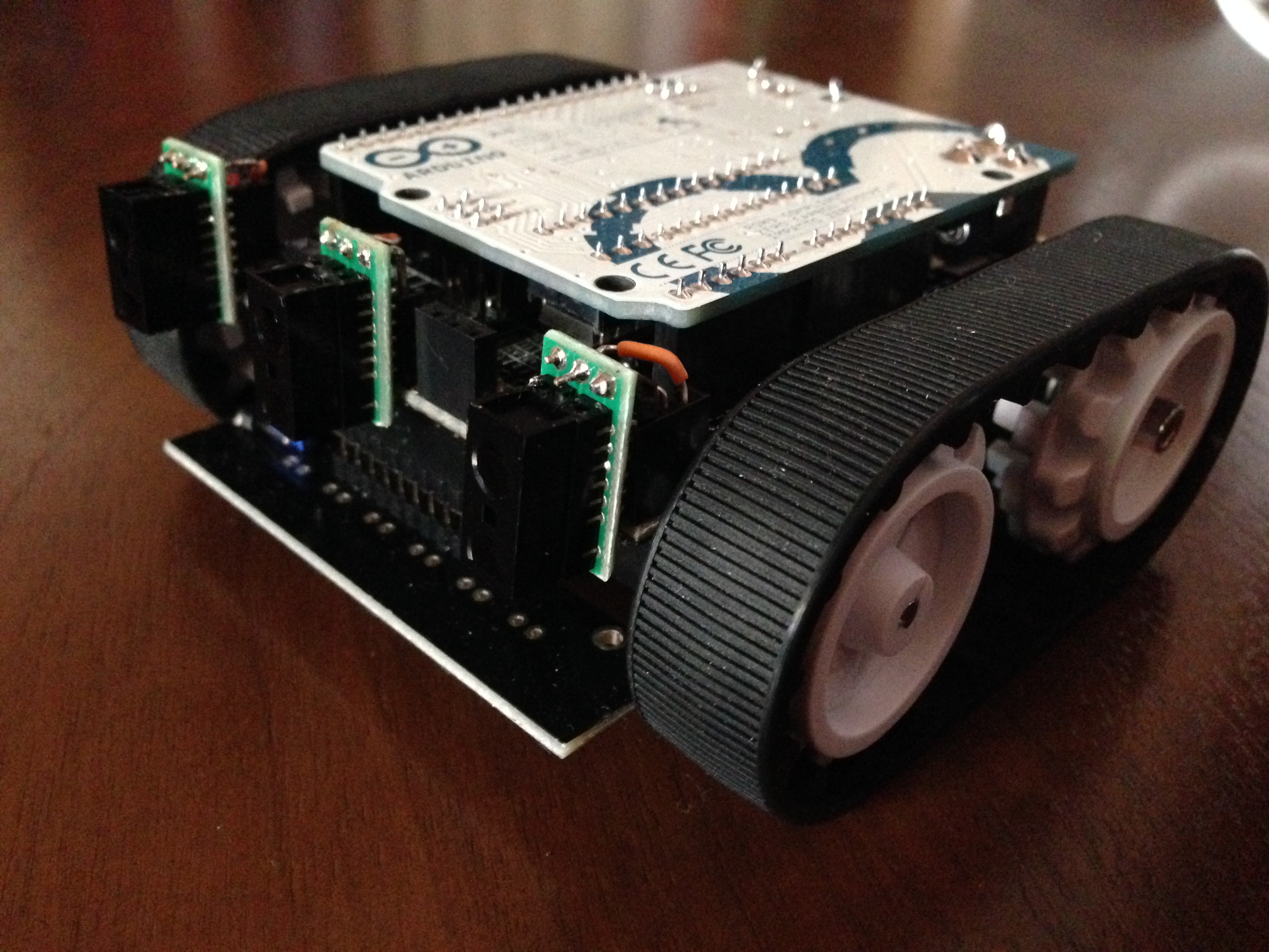
Here’s what I’m currently planning to use for this project:
2. Pololu Zumo Shield with Robot and Reflectance Array
3. Three Sharp Digital Distance Sensors 5cm
4. Adafruit Bluefruit EZ Link Shield with Stacking Headers
A note on Adafruit’s Bluefruit Shield: I received mine not too long ago, and I experienced a lot of issues using it on a Macbook. Adafruit has acknowledged this issue, and released a software patch [5], but it didn’t fix everything for me. They’re currently working on making an entirely new board that fixes the issue without a software patch. Adafruit’s customer service was amazing on this issue. They refunded the purchase price and let me keep the board just in case I decide I have a use for it.
Thanks for following my progress on this project!
References
0. https://www.sparkfun.com/tutorials/219
1. http://arduino.cc/en/Reference/digitalRead
2. http://arduino.cc/en/Tutorial/AnalogInput
3. http://arduino.cc/en/Tutorial/PWM
4. http://www.amazon.com/Programming-Arduino-Getting-Started-Sketches/dp/0071784225
5. http://forums.adafruit.com/viewtopic.php?f=31&t=47431